In this final blog post of our Solar + Energy Storage series, we will discuss how to properly size the inverter loading ratio on DC-coupled solar + storage systems of a given size.
How to optimize your inverter loading ratio for solar + energy storage projects
James Mashal, Taylor Sloane, and Colleen Lueken | Fluence Energy
Reposted with permission from Fluence:
In this final blog post of our Solar + Energy Storage series, we will discuss how to properly size the inverter loading ratio on DC-coupled solar + storage systems of a given size. In previous posts, we discussed the fundamental drivers for pairing energy storage with solar, the reasoning behind DC-coupling solar and storage, and how to calculate the optimal ratio of solar and storage for a given application.
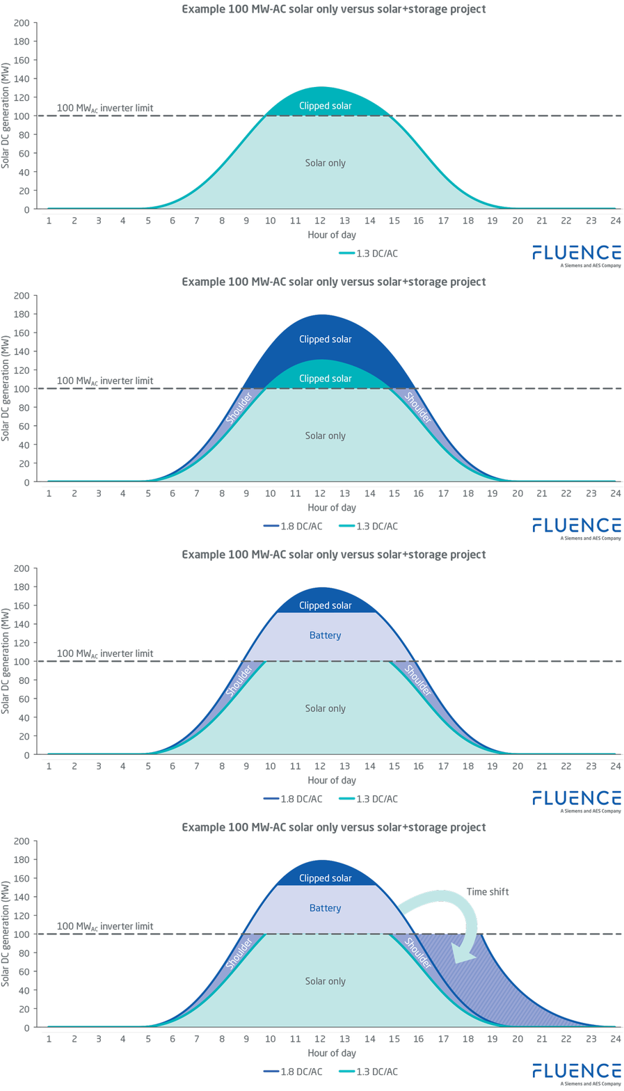
One of the main benefits of DC coupling is enabling more energy to be delivered to the grid by storing energy that otherwise would have been clipped. In most regions, solar developers already overbuild their systems with extra PV panels to increase the total energy output of the system. For example, it is typical to see solar projects with 1.3 MW of PV panels per 1 MW of inverter capability. This oversizing of the PV panels in relation to the inverter size will maximize the total energy output of the system throughout the year, particularly during months with reduced solar irradiation. Unfortunately, increasing the inverter loading ratio, which is the DC capacity of the solar panels divided by the AC capacity of the inverter, leads to some energy being lost or clipped during the sunniest hours of the year.
INVERTER
|
= |
DC Capacity of Solar PanelsAC Capacity of Inverter |
One of the advantages of a DC-coupled solar + storage system is that the battery can store this energy that would normally be clipped, while an AC-coupled system cannot. Furthermore, a DC-coupled solar + storage system will allow the developer to increase the overall inverter loading ratio for the project, which increases the amount of delivered energy to the grid without the risk of clipped energy. See figure below:

Note: We're about to get into the nitty gritty of the specific details of solar + storage sizing and system design, so hold on to your hat! (Or call us if you get stuck.)
Once you have decided on the size of your energy storage system, you now need to decide how many panels and inverters to install in order optimize the cost. This optimization will take into account the additional energy a DC-coupled system can deliver. The optimization is similar to the one done for solar-only projects, with a minor increase in complexity to account for the state of charge of the energy storage. The inverter loading ratio determines the amount of additional energy that can be cost-effectively sold. Generally, the maximum inverter loading ratio for solar + storage systems will have their output limited by:
- Land: a limited amount of land on which to install solar panels
- Interconnection: an interconnection agreement which limits the amount of power they can inject into the grid
- Economics: will there be enough additional revenues to cover the extra costs and a reasonable rate of return
Imagine a project developer who followed the steps in our previous blog post to determine she should pair a 50 MW/4hr storage system with her 100 MW (AC) solar project. Based on this configuration, she is unsure about the optimal inverter loading ratio for the project and ultimately how many solar panels she should buy. The project will be limited by the 100 MW interconnection and she has space to add up to 250 MW (DC) of panels, so economics will determine the best inverter loading ratio.
To perform the analysis, she can follow these steps:
- Revenue: Determine the additional revenue that can be earned at different inverter loading ratios
- Determine the amount of energy delivered at different inverter loading ratios. This will require a granular analysis, likely at the hourly level, to determine how much energy is delivered for different inverter loading ratios, either from adding more panels or reducing the number of inverters. We recommend you start with the inverter loading ratio you would use without storage, which is commonly 1.3. The simplest analysis for each hour would be:
Delivered Energy = Min (DC Solar Generation, Inverter Size + Battery Capacity)
Note: Battery capacity will need to account for the battery power ratings and hourly state of charge. Detailed analyses should also account for losses of the different equipment.
Depending on the storage size, the battery will be able to absorb all the energy, but on the sunniest days, it likely will not be able to absorb all of it. The analysis should also take into account timing the delivery of energy to the grid according to the energy offtaker’s preferences. This step requires detailed modeling of the dispatch of the combined battery and PV system, and is often the most time consuming. - Determine the marginal change in energy delivery for change in inverter loading ratio. Determine how much energy is delivered for each increase in inverter loading ratio. For example, if the total energy delivered for a 1.6 inverter loading ratio is 254,400 MWh and for a 1.7 inverter loading ratio is 269,600 the marginal change in energy delivery is 269,600 MWh - 254,400 MWh = 15,200 MWh.
- Determine the value of firm and non-firm solar energy. This will be based on the costs of existing generation, tariff price, expected PPA price, and/or the costs expected for other projects that could be substitutes. For this project we will assume the value of firm and non-firm solar energy are both $50/MWh. Note that most projects pairing storage with solar PV will value the dispatchability of the combined asset, necessitating variable pricing for energy delivered in different times of day.
- Determine the value of the marginal energy changes. For each inverter loading ratio, multiply the value of the energy calculated in step 1c ($50/MWh) by the marginal energy calculated in step 1b.
- Determine the net present value of these cash flows across the length of the contract.
- Determine the amount of energy delivered at different inverter loading ratios. This will require a granular analysis, likely at the hourly level, to determine how much energy is delivered for different inverter loading ratios, either from adding more panels or reducing the number of inverters. We recommend you start with the inverter loading ratio you would use without storage, which is commonly 1.3. The simplest analysis for each hour would be:
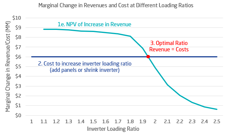
- Determine the additional costs for changing inverter loading ratios. If you are interconnection limited, determine the marginal increase in costs (including balance of plant) for adding more panels to increase the inverter loading ratio. If you are land limited, determine the marginal decrease in costs of the inverters and other balance of plant equipment for each increase in the inverter loading ratio. The developer in our example is interconnection limited and she estimates that it will cost an additional $600/kW to add additional panels and the corresponding DC balance of plant. To increase the inverter loading ratio by .1 it requires an additional 10 MWdc, which costs $6 million.
- Determine the inverter loading where the value of the marginal energy increase/decrease equals the marginal costs/savings. As shown in the figure below this occurs for our developer at a 1.9 inverter loading ratio. At this point the cost of adding more panels is recovered, including a rate of return, by the additional energy that can be captured by the energy storage.

Following the steps outlined above, project developers can optimize the inverter loading ratios for DC coupled solar + storage projects, enabling them to offer lower cost systems to customers and increase the returns of investors.
About James Mashal
James Mashal is an Analyst, Taylor Sloane is an Associate, and Colleen Lueken is a Director on the Market Applications team at Fluence. They identify markets and applications that are attractive for energy storage development.
The content & opinions in this article are the author’s and do not necessarily represent the views of AltEnergyMag
Comments (0)
This post does not have any comments. Be the first to leave a comment below.
Featured Product

